Follow this Technical Manual to convert the old ice bank control, part #S0513-A to the new style ice bank control, part #S0068-U. The old style ice bank control came standard in all Crysalli models made in 2019 and prior. Beginning in 2020, the new style ice bank control, part #S0068-U comes standard when you purchase a new water chiller. If you run across an old style control, follow these steps to successfully convert to the new standard ice bank control. Go to the bottom to download a "printer friendly" version to use
Removal of original mechanical Ice Bank Control (IBC)
- Shut off water, power and CO2 to the Crysalli system
- Remove lid from chiller
- Remove white pipe stem to drain the water bath
- Allow the ice bank to defrost completely
- Defrosting the ice bank can take ~24 hours. Shut the power off the day before service
- Warm water can be poured over ice bank to speed up the melting process or you can use a hairdryer to melt the ice bank.
- Do not use screwdriver, pick or sharp object to break ice bank
- Remove the screws and move the front/bulkhead panel to access electrical board. Remove the cover plate for the electrical box.
- Next, remove the side panel to access existing ice bank control
- For the CR-2 & CR-UCM2 series units you will access the electrical board through the rear panel or panel on the opposite side of the bulkhead panel.
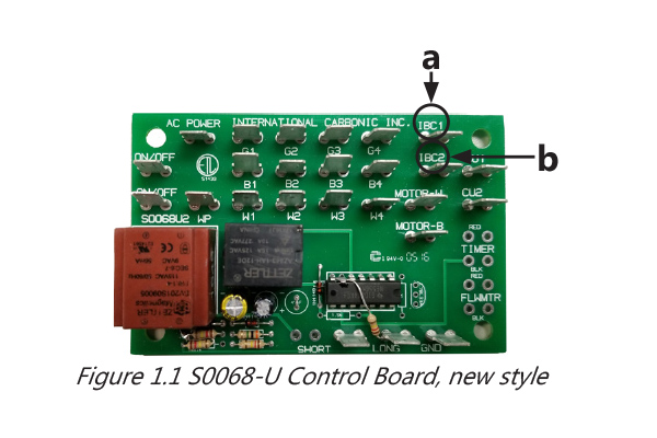
- Using needle nose pliers, remove terminal plugs from IBC1 (Fig 1.1 item a) & IBC2 (Fig 1.1 item b)(sparkling water systems)
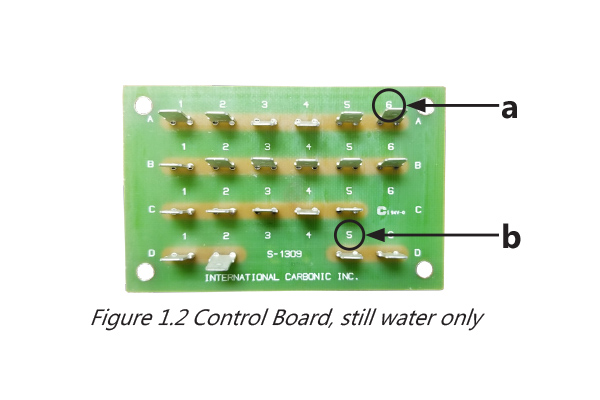
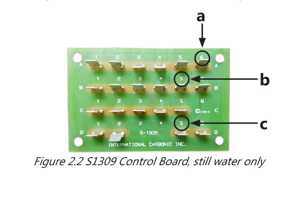
- For “still water only chillers” remove terminal plugs from A6 (Fig 1.2 item a) and D5 (Fig 1.2 item b)
- Remove the ice bank control from mounting bracket
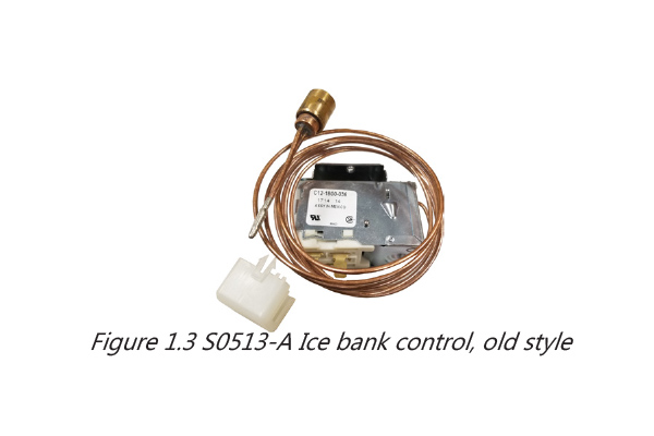
- When the ice is completely melted from the evaporator, remove the ice bank bulb and bracket (Fig 1.3)
- Now you can completely remove the ice bank control assembly from the Crysalli system
Installation of new electronic Ice Bank Control (IBC)
- The electronic ice bank control is programmed by Crysalli to the settings designed for the Crysalli water chiller systems
- Do not substitute for other IBC models
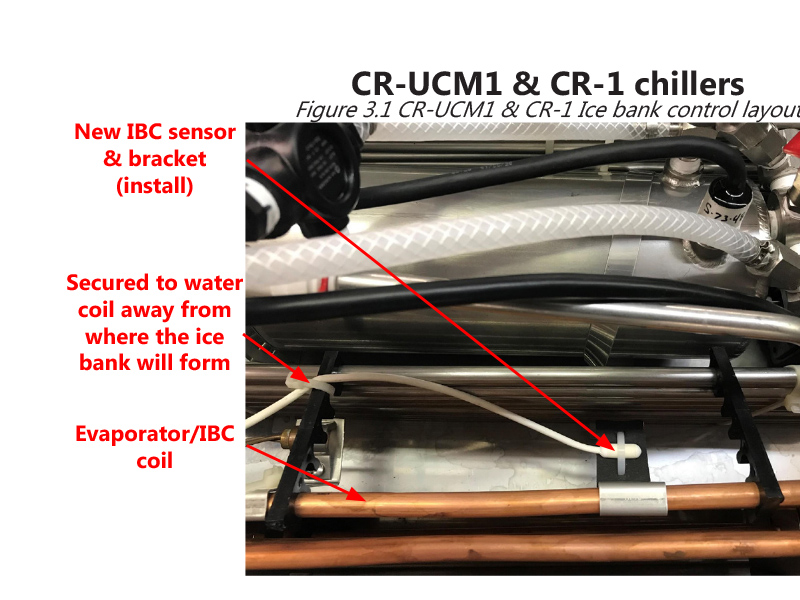
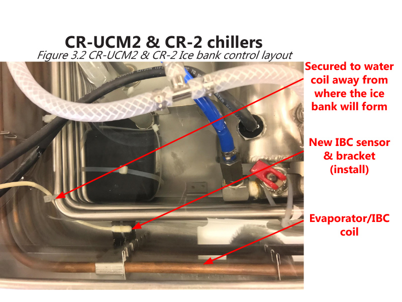
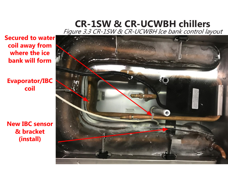
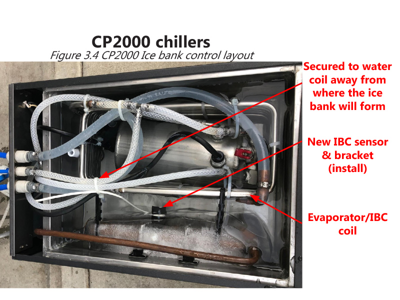
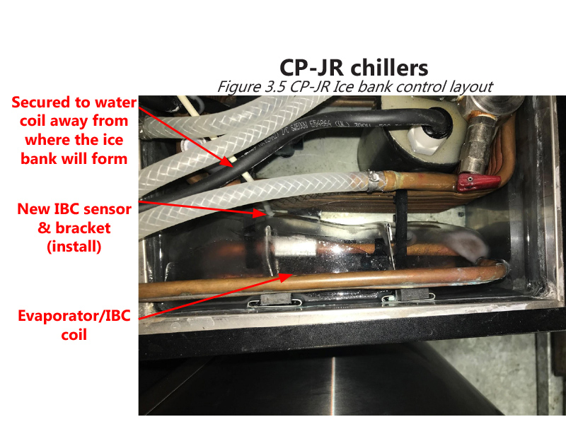
- Attach the WHITE thermal control sensor & bracket to the evaporator coil in the water bath
- Each Crysalli model has a specific location for mounting the sensor bracket to the evaporator to maintain a uniform ice block formation
- See pictures (Fig 3.1-3.5) of the different models and locations and cross reference it to the model you are working on
- After identifying the correct location secure the sensor bracket to the evaporator coil using the supplied zip tie
- Use the zip ties provided to secure the white thermal control sensor wire to the water coil (Fig 3.1-3.5)
- Do not leave slack in the control sensor wire and make sure the wire is secured to water coil away from wher the ice bank will form
- *NOTE: If the thermal control sensor wire freezes within the ice bank it will send false readings back to the electronic controller cycling the compressor off prematurely
- Route the thermal control sensor wire back to the electronic controller and plug the terminal connector into the thermal control box
- Attach the electronic IBC control box to the same mounting bracket where the original ice bank control was located
- Zip tie any slack wire keeping it clean and away from any moving parts within the condensing system
- Route the brown, black and white wires from the IBC control box to the Crysalli circuit board
Sparkling water system wiring
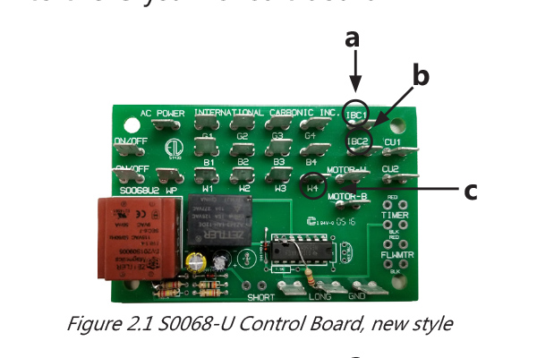
- Connect the BLACK wire to terminal IBC1 (Fig 2.1 item a)
- Connect the BROWN wire to terminal IBC2 (Fig 2.1 item b)
- Connect the WHITE wire to terminal W4 (Fig 2.1 item c)
Still water system wiring
- Connect the BLACK wire to terminal A6 (Fig 2.2 item a)
- Connect the BROWN wire to terminal D5 (Fig 2.2 item c)
- Connect the WHITE wire to terminal B5 (Fig 2.2 item b)
*NOTE: If the unit has a different circuit board than what is shown, call the Crysalli service manager for wiring details
Start up system
- Reinstall the white pipe stem
- Reinstall and secure all panels that were removed
- Fill the water bath to 1/4” below the top of the white pipe stem
- Turn on the water, power and CO2
- Listen for the compressor to kick on
- Install lid
- Allow for 3-4 hours for the ice bank to form
Ice Bank Control (IBC) sensor & bracket location
pdf Printer Friendly Version (1.53 MB)